Equipment
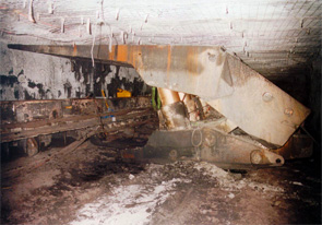
Chocks (also known as "Powered Supports",
"Supports" or "Shields")
Roof support in early longwalls (in the days of hand
mining) was by timber props and bars, withdrawn from the goaf side as the faces
advanced and re-used if still intact. Eventually these were replaced by steel
bars supported by yielding props (eg friction props where resistance to yield
was provided by a wedge system or hydraulic props which were individual props
filled with fluid which could be pumped with an internal hand pump and released
using a valve).
In time the hydraulic props (now referred to as legs)
were combined in pairs, mounted on a base and joined with a roof canopy, with adjacent
pairs being connected by a frame containing a horizontal hydraulic cylinder.
This enabled each "chock",
as the 4 leg sets were
called, to advance itself with one pair of legs, released from the roof,
pushing against the 2nd pair which remained set. Such chocks were
set along the length of the face forming a continuous line of "self-advancing
supports", sometimes also
referred to as "goal post supports or chocks".
Simplified sketch of "goalpost chock"
Further development saw the legs being mounted closer
together on a single solid base with a solid, cantilevered roof canopy allowing
the front line of legs to be a little further from the face while still
providing adequate support close to the freshly exposed roof. The horizontal
cylinder in these chocks attached the chock base to the face coal haulage
system (an AFC – see later notes). The cylinders were used to push the
AFC forward and then drag the chocks forward one at a time as the face
advanced. The chocks were interconnected with hydraulic hoses and connected
back to a pumping arrangement in the gate road by a hydraulic fluid reticulation
system. The hydraulic fluid used was (and still is) mostly water with a low
concentration of soluble oil, partly to assist in lubrication but mostly to
inhibit corrosion. At times 6 leg
chocks were used with 4 close together at the rear and 2 close to the AFC,
leaving a travelling way between them.
Simplified sketch of early longwall chock
Over time the rear of the chocks was partially
closed-in with flexible arrangements of steel plates, chains and timber to try
and prevent broken material from flushing through from the goaf into the face
area.
Similar support systems were developed where the 4
vertical legs were replaced by 2 larger legs set at the rear of the base and
angled towards the face. These had a somewhat larger canopy with a rear section
connected to the base with a "lemniscate" linkage which enabled the base and
canopy connection to be fully covered, while the main canopy remained
essentially parallel to the base at whatever set height was used. These supports
were called "shields" instead
of chocks.
 Again, over a period, further developments combined
the best aspects of chocks and shields into what were referred to as "chock-shields" but are now often referred to using either
term by itself, but the terms "supports" is probably the most common term now
used (and the term used in this document).
Most modern supports are two leg types, though four
leg shields and chock-shields are also in use, all four legs mounted towards
the rear of the base with the front pair angled towards the face and the rear
pair towards the goaf.
The rear section of the chocks which contains most of
the operating valve systems and the legs, is partially covered by side plates
as well as being enclosed from above and behind. These side plates have a top
cover and can slide sideways, pushed by small hydraulic cylinders, so that the
chocks can stand skin-to-skin and provide continuous cover over the full length
of face.
In a further development the front tip of the roof
canopy is articulated and connected to another small cylinder allowing a
greater load to be applied to the roof at this point to improve roof control.
For thick seams, where coal falling from the face can
be a hazard supports can be fitted with an articulated plate attached to the
support tip which can swing down and provide a horizontal support to the
exposed face. Once again this is controlled hydraulically and obviously has to
be lifted clear again before the next web of coal is cut.
Most modern supports are fitted with "base lifters" another hydraulic arrangement which allows
the base to be lifted up, a very useful function in soft floor conditions where
support bases may sink into the floor and limit the ready advance of the face.
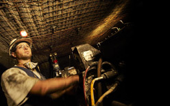
Modern supports are very complex pieces of equipment,
made even more complex by the primary method of operation being via remote
control or automated, requiring electronic control and monitoring, with manual
control also being fitted. Longwall faces are also now extensively illuminated
and these functions require hydraulic and electrical connections from support
to support and back to the maingate area, a typical face carrying many hoses
and cables. The hoses and cables between supports need to be flexible and have sufficient
length to allow for the distance any support will be advanced ahead of adjacent
supports.
Because of the high setting pressures of modern
supports a two stage setting system may be used, an initial "low pressure" set
(of the order of 320 bar) being boosted to the final set by a high pressure supply
(of the order of 420 bar) - yet another set of
hoses to be included.
Supports are designed to operate through a range of
heights to accommodate variations in working heights and possibly some degree
of unplanned loss of roof or floor. It is also necessary that they can be
closed down low enough to allow transport around the mine in whatever height is
available. Support legs are often multi-stage legs to allow additional travel.
Support widths vary, mostly between 1.5 and 2m. Note
that as a chock is made wider the load/metre run along the face which can be
applied to the roof reduces for a given leg capacity. Also the wider a support,
the heavier it becomes and more difficult to handle. As a support is made
narrower it becomes less stable if subjected to uneven ground. Also the
narrower a support, the more supports are required for a given face length and
with each support requiring a set of control valves and interchock hoses, so
the greater the cost. The ideal support width will be the best compromise
between the conflicting aims.
An aspect of support design beginning to receive more
attention is ergonomics. When a face is "closed-up", especially in lower height
seams, travelling along the face can be very arduous. To increase the width of
walkways involves extending the length of the supports which has ramifications
on roof loading and strata control (as well as costs), so some degree of
compromise is required.
There is a tendency to design for "average" size
personnel which, by definition, means that half the workforce are likely to
experience some difficulty or discomfort. It may be better, within reason, to
design for the tallest and widest person likely to travel the face. Allowance
has to be made for equipment being carried on a regular basis (cap lamps, self
rescuers, etc).
The purpose of the roof supports on a longwall face is
not to prevent roof movement but to control it so that the immediate roof
remains essentially intact where the coal is cut and within the area of the
face where personnel have to work. Once the work area has moved forward it is
acceptable, indeed desirable, that the roof collapses or "caves" (a term frequently used). The ideal
situation is that the roof caves immediately behind the supports as they are
moved forward; if the collapse is delayed the roof strata will hang out into
the goaf in a cantilever putting extra load on the supports.
This cantilever effect was largely responsible for
early failures of longwall mining in Australia, circa 1970. Supports at that
time had been developed in Europe where roof strata was generally weaker and
laminated and caved readily. Support loading capacities of 100 tonnes or less
were adequate to control the roof. In Australia more massive strata is common
which breaks and falls less readily and the cantilever effect leads to very
high chock capacities being required, sometimes over 1000 tonnes.
In order to prevent damage to the hydraulic legs,
chocks are designed to yield (ie release the hydraulic pressure) at a set
value, so the roof is allowed to lower in a controlled fashion.
For best roof control a high chock set pressure is
required, as close as possible to the yield pressure – it is not
practical to set at the yield pressure.
As the roof lowers, the strata above will begin to
bend and then beds will fracture under tension from the higher levels extending
down towards the immediate roof (these fractures being known as "goaf
breaks"). Ideally these
fractures should reach the roof as the rear of the supports passes that point,
allowing immediate caving.
Ideal formation of roof fractures, reaching seam roof at rear of support
If it
occurs ahead of this point then the roof above the chocks will break-up and
this may give rise to problems on the face itself. Broken roof above the
canopies is not usually a big problem as the broken strata will remain more or
less in place as long as the chocks are not lowered away from the roof when
they are moved. Broken roof ahead of the canopies can lead to total loss of
control and major falls on the face itself.
Cavities or broken roof above the canopies can result
in:
- not being able to set the
supports to the roof at the designed set pressure because the canopy has to
remain reasonably level; if there are cavities one end of the canopy may push
up into the cavity causing the other end to come away from the roof
Sketch to show effect on support setting (if full pressure set used) of cavity in roof over chock
-
very high point loads
at contact points between strata and canopy which have to take the share of
load which cannot be transmitted through the cavity.

